
How Do You Build a Collector?


Psionic Mushrooms’ Solar Heat Collectors
How to Build:
Materials (large model):
1 sheet of 4’ x 8’ x 1/2” plywood
3 studs, 2” x 4” x 8’
(optional) 1 furring strip 1” x 2” x 8’
289 regular sized aluminum cans
(32 ft2) of polycarbonate sheeting to fit the design
1 Gallon Matte black paint (We use Olympic brand)
1 box 1” black anodized Screws
8 self tapping screws 3”
1 Computer Fan
Low voltage wiring and quick tab connectors
1 Thermoresistor set to 75 degrees Fahrenheit
(Optional) 24’ of 3/4” angle aluminum, or 24’ of white aluminum flashing
(Optional) 22 self tapping 1” metal screws
2 tubes of Project liquid nail (10 oz)
1 electric solar panel, or 1 12 v 1 amp power supply.
1 4” spring loaded baffle vent
Tools:
1 Power drill
(Optional) 1 Screw Gun
1 Caulk gun
1 Straight edge
1 Measuring tape
1 Step bit (up to 7/8”)
1 Hand saw (optional, 1 circular saw)
Gloves and Goggles
(Optional) Soldering gun
1 Pair of wire cutters / strippers
1 Pair of pliers
1 4” hole saw
1 Paint spray gun
Can preparation:
1. Take a standard size aluminum can and take the tab off.
2. After removing the tab from the can wash the can with water.
3. Flip the can over, and drill a 7/8” hole in the center of the bottom of the can.
4. Place the can in a tub of water to remove the metal shavings from inside, the water tub will prevent the metal shavings from being washed into the sink drain on its second rinsing.
5. Dry the cans off and put them aside for later.
Assembly (large model):
Box construction:
1. Place two 2x4 studs on either long side of the plywood sheet.
2. Use one and a quarter inch screws and screw the studs every four inches so that they are lined up and attached to the edges of the plywood board.
3. Measure the space between the two plywood beams. If the boards are screwed in correctly, this space should be about 45 inches wide.
4. Using the remaining 2x4, cut two 45 inch sections out of it (or two sections that fit snugly between the 2x4s on the edges of the plywood).
5. Measure 7.5 in from the smaller edge of the plywood sheet and draw a horizontal line all the way across the board. Do this on both sides of the board
6. Place the two 45 inch boards on either side of the plywood sheet so that they are flush with the outside edges. Screw them in securely. You should now have 2x4s outlining the edges of the plywood sheet.
7. Drill two 4 inches in diameter holes on opposite sides and opposite corners of the plywood sheet. The holes should be 1 inch away from the edges of both 2x4 boards. Clear away the excess saw dust left over with a vacuum cleaner. Storing cans in the collector is an efficient way to protect them.
8. Also on the long side of the collector near the fan hole, drill a small hole for the fan wires to come out of the 2” x 4”. It should be about 2 inches up from the plywood and about 5 inches from the end of the 2” x 4”.
9. Using the glue gun, apply a strip of glue beginning at one of the lines drawn in step 4, and continuing until the other line. The strip of glue should be about 1.25 inches from the inside edge of the 2” x 4” to obtain maximum adhesion to the can since the cans are 2.5 inches wide.
10. Start applying cans to the strip of glue so that the bottom of the first can lines up with the step 4 lines. All cans should be facing the same direction and the bottoms and tops should interlock
11. Apply the next strip of glue 2.5 inches from the previous strip of glue, so that it is parallel with the existing line of cans. Place cans on this column the same way as done the first time.
12. Repeat this glue strip and can column process for the remaining columns. It is optional to add the 1” x 2” furring strip above and below the cans. This strip will help support the cans.
13. Fill the paint spray gun with black paint making sure that there’s nothing obstructing the flow from the paint container to the nozzle.
14. Cover the inside of the solar heat collector (SHC) with a coat thick enough that it’s all black and none of the color from the layer below is showing.
15. Next, attach the computer fan to the solar heat collector by screwing it in directly over the exhaust hole. Cover the other hole with screen meshing by gluing it in place. This is for bringing in fresh air without insects.
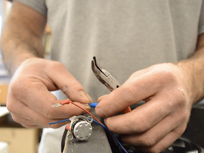
16. For the circuitry, cut and strip the wires. Attach quick tab connectors to all of the wires including a male and female connector for the fan and female connectors on the power supply. Place the male/ male thermoresistor between the female/ female connectors on the fan and power supply. Connect the female power supply to the remaining male fan wire. Carefully glue the wires inside the heat collector, so they don’t pull free. Test the fan/thermoresistor/power supply combo. Make a 6 inch wire with a male and female quick connect tab. Glue the thermoresistor inside the heat collector, attach the extra jumper wire to the thermoresistor and bring it out the hole, bring the extra fan wire out the hole, and retest with power supply. The power supply is NOT inside the heat collector and the wires come out.
17. Next, place the polycarbonate sheeting over the solar heat collector so that the edges of the polycarbonate are flush with the edges of the solar heat collector.
18. Screw in the polycarbonate with one inch anodized screws. Make the screws about four inches apart. It is optional to screw on metal side paneling around the edges of the polycarbonate.
Mounting instructions
1. Mount L bracket on studs of house 48 inches apart vertically.
2. Cut a 4 inch hole in the building for the baffles corresponding to the top hole on the SHC.
3. Insert the spring loaded baffle vent into the hole on the SHC so that when the SHC fan turns on, it will open the vent.
4. Mount the SHC to the brackets and plug in the collector. Depending on the arrangement and power supply, an additional 1/2” hole may be necessary on the house.
This live feed is a live montioring of a solar heat collector. It is achieved by using a circuit assembled by one of our community members, Mr. Kissman, and it monitors collectors that are installed on his house. It is a circuit comprised of an XBee radio connected to an Arduino board, then programmed using the code provided underneath the live feed. If the link does not work to open the PDF, the code is provided below.